Mold design starts with the design of the molded parts, that is, according to the structure, size, and number of mold cavities of plastic parts to arrange a molded part design, including working out the shape and size and the assembly way of the molded parts.
When designing molded parts, the molding characteristics of the plastics(including shrinkage, flow, aggressive, etc.), the parting and demolishing characteristics (including the slope of demolishing, etc.), and the technological characteristics of the manufacture and maintenance should be fully considered.
What are molded parts?
1.1.1 Injection molds can be divided into two parts: moving and fixed, as shown in Fig.1-1. In the mold, the parts can be divided into molding parts and structural parts. Structural components include the mold base, which generally uses ordinary steel. Molded parts use excellent mold steel. Doing so has two purposes: one is convenient for processing and maintenance, and the other is to reduce the manufacturing cost of the mold, guarantee its strength, stiffness, and wear resistance, and make the mold reach its predetermined production life.
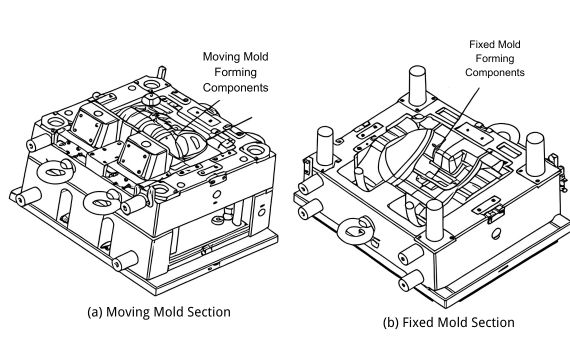
Figure 1-1 Injection Mold for Automotive Rearview Mirror Housing
In mold production, the space used to fill the plastic melt and form the plastic part is called the cavity. The mold parts that constitute the cavity part of the injection mold are collectively referred to as molding parts, also known as internal mold inserts. Internal mold inserts include fixed mold inserts, moving mold inserts, and core pins. In addition, molding parts include lateral core-pulling mechanisms, inclined push rods, and ejector parts. In Figure 1-1, the moving mold inserts, fixed mold inserts, and sliders are all considered molding parts. This chapter mainly describes the design of internal mold inserts in injection molds, including the design of parting surfaces, the size of inserts, the method of inlaying and fixing the inserts, etc. The design of lateral core-pulling mechanisms and ejector parts will be discussed in other chapters.
1.1.2 Basic Requirements for the Design of Molding Parts
The basic requirements for mold molding parts include the following.
(1)Sufficient strength and stiffness
In injection molding, the cavity must withstand the high pressure of the high-temperature melt, so the mold cavity should have sufficient strength and stiffness. If the cavity strength needs to be increased, plastic deformation will occur, even fracture; the stiffness needs to be increased, elastic deformation will be too great, leading to transfinite deformation of the cavity outward and causplastica part stuck in the fixed mold or flash appearing at the parting line. Conical positioning is often added to the design in increasing molding parts, as shown in Figure 1-2.
(2)Molded plastic part that meets the requirements can be obtained
These requirements include appearance shape, dimensional accuracy, surface roughness requirements, emotional mechanical property, chemical property, etc.
(3) The plastic part produced can be directly used in the assembly, avoiding the following machining of molded parts. Through structure design of molded
All slots, self-tapping screw columns, snaps, inserts, and so on should be designed to be molded one time in the cavity.
(4)Reliable molding, high efficiency. The design of molding parts should consider a fast-filling gating system, fast cooling of other molded parts, quick and reliable ejection, and easy takedown of other runners and gates.
(5)Low manufacturing cost.
The structure should be simple, reliable, and practical, shortening the production time and reducing manufacturing costs, as shown in Figure 7-3.
(6)Easy to maintain and repair.
For areas prone to damage and difficult to machine, an insert structure should be considered to allow quick replacement after damage, as shown in Figure 7-4. A mold is a long-lasting production tool, so future maintenance and repairs must be considered during the design phase.
(7) Material aspects.
- The material should have sufficient hardness and wear resistance to withstand the friction of the material flow. Typically, the hardness of the core mold material should be above 35HRC. For molds used in the injection of glass fiber-reinforced plastics or for high-volume production, the hardness of the core mold inserts is often required to be above 50HRC.
- The material should have good polishing performance. The surface roughness Ra is generally required to be below 0.4 μm. The cavity surface should be mirror-polished for molds producing transparent plastic products, with a surface roughness Ra requirement below 0.2 μm.
- The material should be easily machinable for cutting processes. Critical areas and precise fitting parts should undergo grinding processes, while general areas should be processed using turning or milling operations.
1.1.3 Design Content and General Steps for Forming Components
The design of forming components generally follows these steps:
- Determine the number of mold cavities.
- Identify the plastic product’s parting line and the mold’s parting surface.
- Determine the arrangement of the cavities.
- Design the side core-pulling mechanism if side core-pulling is required.
- Define the forming dimensions of the core and cavity and establish the draft angle for demolding.
- Determine the assembly method and fixation method for the forming components.
This chapter thoroughly discusses the other five steps and explains the design of the side core-pulling mechanism in detail in Chapter 9.
1.2 Determining the Number of Cavities
A secondary injection mold can simultaneously produce multiple identical or different plastic parts, significantly increasing production speed and economic efficiency, which are critical values of injection molds. Before mold design begins, preparing a mold separation table is customary. This table must specify the name and quantity of plastic parts to be formed in each mold.
1.2.1 Factors to Consider When Determining the Number of Cavities
The number of mold cavities is usually determined based on the production batch size, the precision requirements of the plastic product, the size of the plastic product, the material used, and its color. At the same time, it is also necessary to consider other factors, such as the plastic molding process, the molding equipment, and the mold manufacturing process. If the number of cavities is not reasonable, it can result in poor melt filling and, in severe cases, even lead to the failure of the entire mold.
Figure 7-5 shows an injection mold for the fuel tank casing of a lighter. A 16-cavity mold is reasonable, but designing for 24 cavities would be unsuitable. Generally, for plastic products with high dimensional accuracy requirements, the number of cavities per mold should not exceed four, and a balanced runner layout must be adopted. For plastic products with standard accuracy requirements, based on experience, even if each cavity produces identical, trim, and easy-to-mold parts, having more than 24 cavities per mold should be carefully considered.
The following factors should be considered when determining the number of mold cavities.
(1)Dimensional accuracy of plastic parts.
Due to manufacturing errors in runners and gates, it is difficult to simultaneously adjust all cavities’ injection process parameters to the optimal values, even if the runner layout is balanced. This makes it challenging to ensure shrinkage consistency. The interchangeability of plastic parts with high precision requirements will be seriously affected. Some foreign studies show that the dimensional accuracy of molded parts decreases by 5% for each additional cavity.
(2)Economic reasons.
The more cavities a mold has, the larger its overall size, requiring a giant injection molding machine. Large injection molding machines are expensive, and their action speed is low, which is not conducive to applying multi-cavity injection molds. Besides, the more cavities a mold has, the higher the mold’s manufacturing cost and the more complex the structure is. Therefore, it is more challenging to ensure the quality of the mold.
(3)Molding process.
The more cavities, the longer the runner. Before the melt arrives in the cavity, the injection pressure and the melt heat will lose a lot. If the size of runners and gates is not designed reasonably, some cavities can not be filled, or even if they can be filled, defects such as weld lines or interior voids will appear. If the injection pressure is increased, a flash will appear in the other cavities.
(4)Mold maintenance and repair.
The more cavities, the higher the failure rate. Once a cavity has a problem, it must be repaired in time. Otherwise, the mold’s original pressure and temperature balance will be broken, which may cause permanent damage to the mold and injection molding machine. Frequent downtime for mold repair also harms production efficiency and mold productivity.
1.2.2 Other Factors to Consider When Determining the Number of Cavities
(1) Production Batch Size, Part Precision, Size, Material, and Color
For small production batches, the number of mold cavities should be minimized to reduce costs. In such cases, plastic parts of the same material, color, and small size can be combined in the same mold for production. For large production batches, assigning the same plastic part to the same mold for production is preferable, i.e., a multi-cavity mold where each cavity produces identical parts.
For example, in the case of disposable lighters:
- The casing parts are produced with a 16-cavity mold.
- The trigger parts are produced with a 24-cavity mold.
- The seal face valve parts are produced with a 12-cavity mold, and so on.
Fewer cavities—generally no more than four — are better for parts with high precision requirements. The size of the plastic part also directly affects the number of cavities per mold. Large plastic parts are better suited to a single-cavity mold, while small plastic parts are suitable for multi-cavity molds. However, the mold size should not be huge, and the length and width dimensions should generally not exceed 300mm × 400mm.
1.1.3 Design Content and General Steps for Forming Components
The design of forming components generally follows these steps:
Determine the number of mold cavities.
Identify the plastic product’s parting line and the mold’s parting surface.
Determine the arrangement of the cavities.
Design the side core-pulling mechanism if side core-pulling is required.
Define the forming dimensions of the core and cavity and establish the draft angle for demolding.
Determine the assembly method and fixation method for the forming components.
This chapter thoroughly discusses the other five steps in addition to explaining the design of the side core-pulling mechanism, n detail in Chapter 9,
2.2 Determining the Number of Cavities
A secondary injection mold can simultaneously produce multiple identical or different plastic parts, significantly increasing production speed and economic efficiency, which is one of injection molds’ critical values. Before mold design begins, preparing a mold separation table is customary. This table must specify the name and quantity of plastic parts to be formed in each mold.
2.2.1 Factors to Consider When Determining the Number of Cavities
The number of mold cavities is usually determined based on the production batch size, the precision requirements of the plastic product, the size of the plastic product, the material used, and its color. At the same time, it is also necessary to consider other factors, such as the plastic molding process, the molding equipment, and the mold manufacturing process. If the number of cavities is not reasonable, it can result in poor melt filling and, in severe cases, even lead to the failure of the entire mold.
Figure 7-5 shows an injection mold for the fuel tank casing of a lighter. A 16-cavity mold is reasonable, but designing for 24 cavities would be unsuitable. Generally, for plastic products with high dimensional accuracy requirements, the number of cavities per mold should not exceed four, and a balanced runner layout must be adopted. For plastic products with standard accuracy requirements, based on experience, even if each cavity produces identical, strim, and easy-to-mold parts, having more than 24 cavities per mold should be carefully considered.
The following factors should be considered when determining the number of mold cavities: (1)Dimensional accuracy of plastic parts.
Due to manufacturing errors in runners and gates, it is difficult to simultaneously adjust all cavities’ injection process parameters to the optimal values, even if the runner layout is balanced. This makes it challenging to ensure shrinkage consistency. The interchangeability of plastic parts with high precision requirements will be seriously affected. Some foreign studies show that the dimensional accuracy of molded parts decreases by 5% for each additional cavity.
(2)Economic reasons.
The more cavities a mold has, the larger its overall size will be, requiring a giant injection molding machine. Large injection molding machines are expensive, and their action speed is low, which is not conducive to applying multi-cavity injection molds. Besides, the more cavities a mold has, the higher the mold’s manufacturing cost and the more complex the structures. Therefore, it is more challenging to ensure the quality of the mold.
(3)Molding process.
The longer the runner, the more cavities. Before the melt arrives in the cavity, the injection pressure and the melt heat will be lost a lot. If the size of runners and gates is not designed reasonably, some cavities can not be filled, or even if they can be filled, defects such as weld lines or interior voids will appear. If the injection pressure increases, a flash will appear in the other cavities.
(4)Mold maintenance and repair.
The more cavities, the higher the failure rate. Once a cavity has a problem, it must be repaired in time. Otherwise, the mold’s original pressure and temperature balance will be broken, which may cause permanent damage to the mold and injection molding machine. Frequent downtime for mold repair also harms production efficiency and mold productivity.
2.2.2 Other Factors to Consider When Determining the Number of Cavities
(1) Production Batch Size, Part Precision, Size, Material, and Color
For small production batches, the number of mold cavities should be minimized to reduce costs. In such cases, plastic parts of the same material, color, and small size can be combined in the same mold for production. For large production batches, assigning the same plastic part to the same mold for production is preferable, i.e., a multi-cavity mold where each cavity produces identical parts.
For example, in the case of disposable lighters:
- The casing parts are produced with a 16-cavity mold.
- The trigger parts are produced with a 24-cavity mold.
- The seal face valve parts are produced with a 12-cavity mold, and so on.
Fewer cavities are better for parts with high precision requirements; generally, there are no more than four cavities. The size of the plastic part also directly affects the number of cavities per mold. Large plastic parts are better suited to a single-cavity mold, while small plastic parts are suitable for multi-cavity molds. However, the mold size should not be huge, and the length and width dimensions should generally not exceed 300mm × 400mm.
(2) Size of the Injection Molding Machine
If the injection molding machine that matches the mold has already been predetermined, there are two methods to calculate the number of cavities:
① Determine the Number of Cavities Based on the Injection Capacity of the Machine
The total weight of all cavity parts plus the weight of the runner system material must satisfy the following conditions:
Total weight of cavity parts+Weight of runner system material<Rated injection capacity of the machine×80%
Note: The calculated value must be rounded to the nearest whole number. It cannot be rounded down or adjusted arbitrarily.
② Rated (or Nominal) Clamping Force of the Injection Molding Machine
Assuming the total projected area of all cavities on the parting surface is Aproj (in mm2), the rated (or nominal) clamping force of the injection molding machine is Fclamp, and the average cavity pressure exerted by the molten plastic is Pcav, the relationship is as follows:
Aproj × Pcav ≤Fclamp ×80%
The average cavity pressure Pcav for different plastic melts is listed in Table 7-1.